RF Welding Solutions
Other Services:
- RF Welding Die Design and Fabrication
- Sample Runs for Evaluation
- Process Development
- Validation Support
What is RF Welding in the Simplest Terms?
Dielectric Heating
RF Welding or RF Heat Sealing is a process of bonding thin layers of plastic materials by using radiofrequency (RF) energy.
The RF energy works only on certain types of dielectric materials that have a polar molecular structure, which gets excited in the high-frequency electromagnetic field (EMF) much like food in a microwave oven.
The RF energy heats the material to its melting temperature until the layers meld under pressure between two electrodes, known as RF tooling or dies. The RF tooling uses raised edges designed to create the perimeter welded shape of the final product.
Dielectric or insulator materials are capable of transmitting electromagnetic force without conducting current through. Yet most dielectric materials will leak current when molecules are polarized.
The polar molecules of dielectric materials generally are in random orientation, when there is no electric field. An applied electric field will polarize the material by orienting dipole moments of polar molecules, like the compass needle orienting towards the North.
When the material is in an alternating field (High Frequency or RF Field) some leakage current passes through the material causing a heat called dielectric loss, which results in heating the dielectric material.
The RF welding machine uses a pneumatic press to clamp the material. The RF welding process uses top and bottom molds (RF sealing dies) where the material is compressed and heated in the RF field. When the press closes RF generator is turned on. The RF field forces the randomly oriented material molecules to align in the field direction. The material's leakage current starts heating the material and forms the product between the dies under a clamped force.
Radio Frequency welding is a material joining process on the dielectric loss principle. RF Welding or RF Heat sealing process uses high frequency energy to melt the plastic material with polar molecules placed in between two electrodes (RF Sealing dies). Most commonly used RF frequency is 27.12MHz.
RF Welding Generators are used in the RF Heat Sealing process to melt plastics materials, comprised of polar molecules. Most RF sealing processes use 27.12MHz high frequency. The same frequency is also used in the Ham-Radio Communications Industry hence where the High Frequency (HF) is referred to as Radio Frequency (RF).
ISM Band Frequencies (Industrial Scientific Medical): The frequency used in the RF welding systems is regulated by FCC and generators must comply with ISM frequency guidelines. The large RF welders will usually use 13.56MHz frequency if the platen size exceeds the 1/4 wavelength of the frequency.
RF Sealing Press: The RF Welding station is a stand-alone pneumatic or hydraulic press, which compresses the plastic material between two molds, referred to as RF sealing dies.
RF Welding Process: In simplest terms, RF welders operate much like microwave ovens that heat food. The Microwave excites the polar water molecules and heats the food.
The RF welder on the other hand heats the plastic material that has polar molecules, which get excited by the high frequency energy.
When RF energy is applied to the compressed material between the RF sealing die surfaces (RF Electrodes), in this case the die surfaces act as capacitors and the plastic material as the insulator dielectric materials, the polar molecules get polarized and start oscillating in the alternating electromagnetic field. This movement or inner molecular friction and dielectric loss material heats up and melts the material. As material softens the press further advances to form the bonded section, defined as RF weld thickness. Once the RF energy is interrupted the material cools down by loosing heat through the dies metal surface.

The RF welding press compression force is essential to form the plastic material while it's melting, where the shape of seal area is controlled by the shape of RF sealing die. The sealing area and the material type dictates the compression force.
Larger the seal area the force has to be larger. Yet it is difficult to control the seal thickness by only force or RF power and time.
There are other factors that can affect the seal thickness, such as material initial temperature, die sealing surface shape or even the humidity level.
It is common practice to use hard stops to control the seal thickness and have slightly higher pressure to achieve RF seal consistency.
Pressure Related Issues:
To insure a uniform RF seal thickness, the pressure must be controlled properly, the RF sealing dies must be flat and parallel, and finally hard stops must be used in carefully engineered locations to maintain evenness around the perimeter of RF sealed surface.

The RF Sealing power is directly proportional to the surface area of the sealing die and material properties.
A general rule for RF sealing 0.012" thick PVC material in 3 second seal time and 3 seconds cool time the process will require about 250-300 watts of RF power.
There are several other factors that can affect the seal quality besides the power over the seal area, are:
To ensure a good quality seal, the RF Power must be controlled properly, such that the seal does not come apart due to lack of power or material does not burn due to excess power.

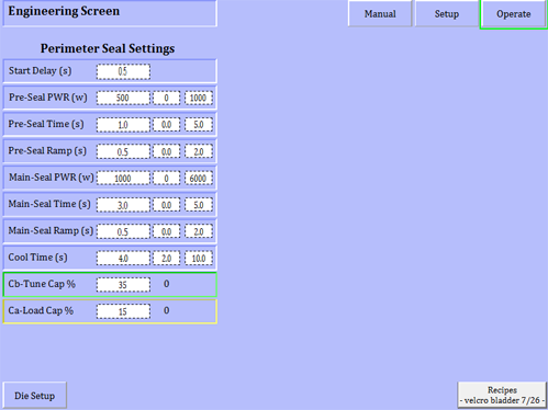
The RF welding process consists of three basic process timers.
The Pre seal time starts when the press is extended all the way down. A limit switch or sensor detects press down position and timer starts timing.
ONEX RF recommends applying minimal RF power like 30-50% of the main-seal power to start melting the material in 1-2 seconds.
After the Pre-seal time, the Main-Seal timer starts timing and RF power is increased to the Main-seal set power.
Some companies would like to apply high RF power to achieve good quality seal in the shortest possible time and experience many inconsistencies.
We have learned the opposite is true. In order to achieve a consistent process control, it is much easier to rely on controlling seconds versus milliseconds, where even the PLC scan time may have an effect on the sealing cycle when using higher RF power.

The cooling cycle is time can affect the seal quality if the RF seal station retracts the press up prematurely while the material is solidifying.
As soon as the RF Main-Seal timer times out the Generator stops the RF energy and material is kept compressed between the dies. The plastic material slowly dissipates heat through the die surfaces. If the process uses insulator materials the cooling cycle will be longer compared with a direct metal contact.
(POLAR & NON POLAR MATERIALS)
Material Type | Excellent, Good, Fair, Poor or None |
ABS polymers | Good |
Acetal (Delrin) | Poor almost None / Used as an Insulator |
Acetal co-polymer | Poor |
Acrylics | Fair |
Aclar | Fair |
APET | Good |
Barex 210 | Excellent |
Barex 218 | Excellent |
Butyrate | Good |
Cellophane | None |
Cellulose acetate (clear) | Good |
Cellulose acetate (color) | Good |
Cellulose acetate butyrate | Good |
Cellulose nitrate | Fair |
Cellulose triacetate | Fair |
CPET | None |
Diallyl phthalate polymer, glass-filled | Poor |
Epoxy resins | Fair |
Ethyl cellulose | None |
EVA | Good |
EVOH (Ethyl Vinyl Acetate) | Fair |
Melamine-formaldehyde resin | Good |
Methyl acrylate | Fair |
Nylon (Polyamide) | Fair |
Pellethane | Good |
PET (Polyethylene Terephthalate) | Good |
PETG (Polyethylene Terephthalate Glycol) | Excellent |
Phenol -formaldehyde resin | Good |
Pliofilm (Rubber Hydrochloride) | Excellent |
Polyamide | Fair |
Polycarbonate | Poor |
Poly-chloro-trifluoro-ethylene | Poor |
Polyester | Poor |
Polyethylene | None |
Polyimide (Kapton) | Poor |
Poly-methyl (Methacrylate) | Fair |
Polypropylene | None |
Polystyrene | None |
Poly-tetrafluoro-ethylene (Teflon) | None |
Polyurethane | Fair |
Polyurethane foam | Poor |
Polyurethane-vinyl film | Good |
Polyvinyl Acetate | Good |
Polyvinyl Chloride (PVC) flexible, clear | Excellent |
PVC color | Excellent |
PVC opaque | Good |
PVC semi-rigid | Good |
PVC rigid | Fair |
PVC flexible glass-bonded | Excellent |
PVC coated material (fabric, cloth or paper) | Excellent |
PVC adhesive emulsions | Excellent |
Rubber | None |
Rubber, compounded | Fair |
Rubber, hevea | Poor |
Saran (Polyvinylidene Chloride) | Excellent |
Silicone | None |
Teflon | None |
Urea-formaldehyde resin | Good |
Barex 210 | Excellent |
Barex 218 | Excellent |
PETG (Polyethylene Terephthalate Glycol) | Excellent |
Pliofilm (Rubber Hydrochloride) | Excellent |
Polyvinyl Chloride (PVC) flexible, clear | Excellent |
PVC color | Excellent |
PVC flexible glass-bonded | Excellent |
PVC coated material (fabric, cloth or paper) | Excellent |
PVC adhesive emulsions | Excellent |
Saran (Polyvinylidene Chloride) | Excellent |
Material Type | Excellent, Good, Fair, Poor or None |
ABS polymers | Good |
APET | Good |
Butyrate | Good |
Cellulose acetate (clear) | Good |
Cellulose acetate (color) | Good |
Cellulose acetate butyrate | Good |
EVA | Good |
Melamine-formaldehyde resin | Good |
Pellethane | Good |
PET (Polyethylene Terephthalate) | Good |
Phenol -formaldehyde resin | Good |
Polyurethane-vinyl film | Good |
Polyvinyl Acetate | Good |
PVC opaque | Good |
PVC semi-rigid | Good |
Urea-formaldehyde resin | Good |
Material Type | Excellent, Good, Fair, Poor or None |
Acrylics | Fair |
Aclar | Fair |
Cellulose nitrate | Fair |
Cellulose triacetate | Fair |
Epoxy resins | Fair |
EVOH (Ethyl Vinyl Acetate) | Fair |
Methyl acrylate | Fair |
Nylon (Polyamide) | Fair |
Polyamide | Fair |
Poly-methyl (Methacrylate) | Fair |
Polyurethane | Fair |
PVC rigid | Fair |
Rubber, compounded | Fair |
Material Type | Excellent, Good, Fair, Poor or None |
Acetal (Delrin) | Poor almost None / Used as an Insulator |
Acetal co-polymer | Poor |
Diallyl phthalate polymer, glass-filled | Poor |
Polycarbonate | Poor |
Poly-chloro-trifluoro-ethylene | Poor |
Polyester | Poor |
Polyimide (Kapton) | Poor |
Polyurethane foam | Poor |
Rubber, hevea | Poor |
Material Type | Excellent, Good, Fair, Poor or None |
Cellophane | None |
CPET | None |
Ethyl cellulose | None |
Polyethylene | None |
Polypropylene | None |
Polystyrene | None |
Poly-tetrafluoro-ethylene (Teflon) | None |
Rubber | None |
Silicone | None |
Teflon | None |

ONEX RF Inc. is dedicated to giving you excellent service with quality results. Expect only excellence.
Copyright © 2020 ONEX RF . All rights reserved.Trademarks, including but not limited to ONEX RF Design are the trademarks or registered trademarks of ONEX RF and used under license by ONEX RF Based on mixed usage scenario.Terms of Use | Privacy Policy